Using TVFool.com as an RF Prep for RF Coordination
Let’s face it, if you are on tour or playing a one-off gig at a venue you have never been to, it is hard getting your RF sorted out before you step foot into the venue. Most of the time you are stuck to guessing what microphone RF bands and doing an RF scan when you get there. I call that damage control!
Being on top of your RF Coordination before stepping into your venue can save you some time and headaches! I’m sure that most of you use Shure Wireless Workbench or IAS from Professional Wireless for your RF Coordination, but how do you know that your data from the Zip Code scan is up to date?
Enter TVFool.com
TVFool.com is a great website if you are setting up an OTA (Over the Air) television antenna because it allows you to look up your home address, enter in the elevation above ground that you mount your antenna, and you press enter. Then a radar display will come up showing where the TV transmitters are located AND it will show you the amplitude that the TV transmitters are potentially going to be received at.
The amplitude part is HUGE because it will show you not only the transmitters that are really strong, but it will also show you the weaker stations. When I am starting my pre-show RF work, I will always enter in the address of the venue into TVFool, save the image, and then print it out. Here is the image that I pulled up for the Viejas Arena:
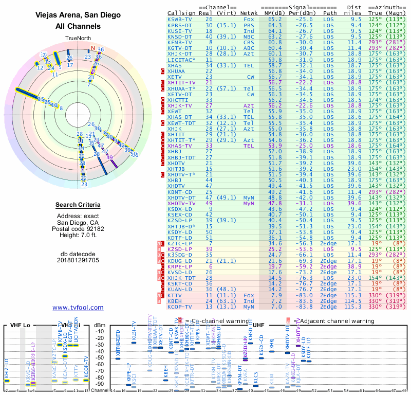
Looking at this, we can see there are a large number of stations in the green part which would be great if we were trying to receive some television! But in our situation, the more stations in the upper green portion would mean a more crowded RF environment.
VHF/UHF Graph:
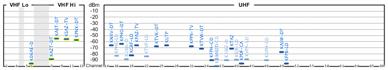
My two favorite parts of viewing this report from TVfool.com happen to be the Radar in the upper left and the graph at the lower part of the image. Let’s take a look at the VHF/UHF graph first:
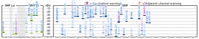
This chart is most helpful for our use because it shows the estimated RF amplitude that the specific television stations will be received at. You can see that dBm is listed in the middle along the Y-axis and the television channel is listed on the X-axis. One can take this information and determine what frequency spans these cover by referencing the Wikipedia page on North American television frequencies, or we can take this information directly into Shure Wireless Workbench.
In the frequency coordination tab, if you right click on the TV channel numbers you can ‘exclude’ a channel from WWB placing a microphone there. With my previous experience, it is best to exclude a channel if it is on the TVFool chart measuring at -70dBm or higher (until you can get a real RF scan to verify).
How Accurate?
So, how closely does this represent an RF Scan? Well, the Viejas Arena is a bad example of this because it is a huge concrete bowl with a TON of steel in the air/roof. But at a recent scan of CCV’s new North Phoenix campus is a perfect example.
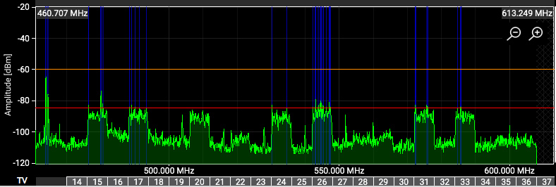
Above is the TVFool chart for the address, and below is the RF scan I performed outside of the building.
When we overlay the two images and warp them to match TV channel number and amplitude scale, we get the following:
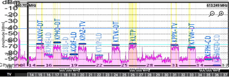
Aside from a few variances, those are pretty darn close. When you add the additional loss you will find from the building walls shielding and attenuating the RF, one could ALMOST do an RF Coordination without a spectrum analyzer. But, if you have access to a spectrum analyzer, please use it. You will have much better results in the long run!
The really cool thing about this is that if you are a church that doesn’t have the budget to get RF scan tools (see my blog post here) then you can at least have a bit of information to empower you for better wireless results!
The Radar Chart
The second thing that TVFool helps with is figuring out where to place your antennas! I have mentioned this before, but a 1000 kW (yes, 1,000,000 watts) is much more powerful than our 20 mW (0.02 watts) wireless microphones. Because of this, we need to maximize our receive of these microphones as much as possible while blocking out TV transmitters as much as possible.
Antennas just like microphones have a polar pattern where they are more sensitive to RF in certain areas. Below is a radiation polar pattern of a Log Periodic antenna:
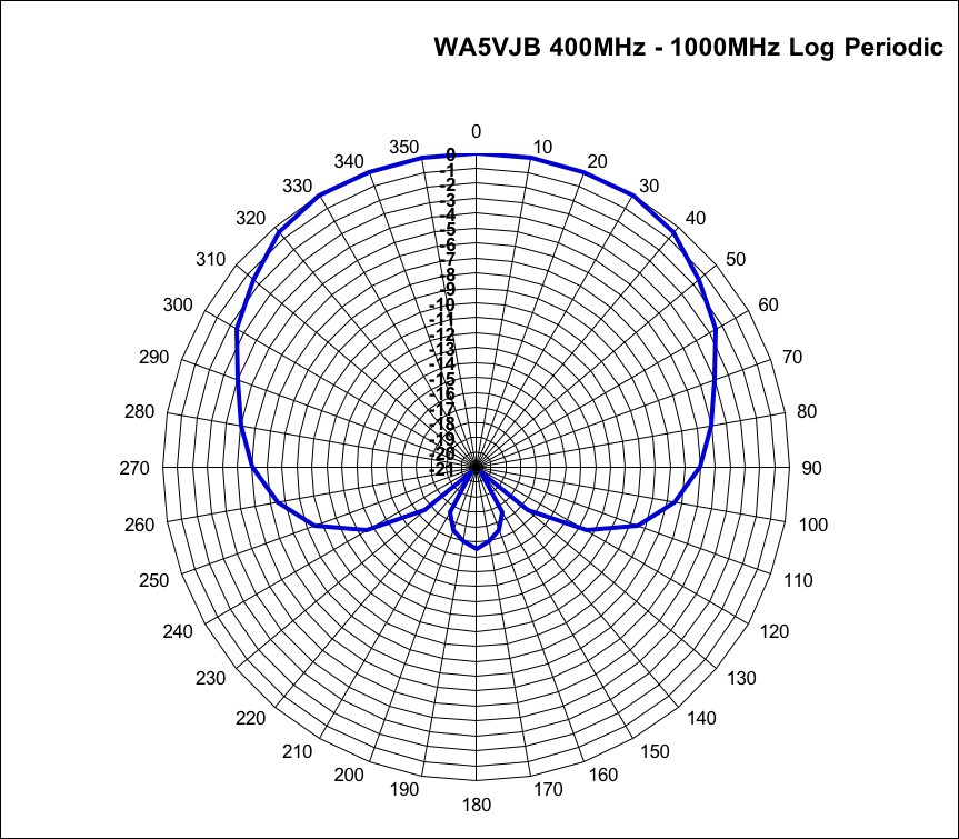
As you can see, it almost looks like a cardioid pattern of a microphone, with a small sensitive area directly behind the antenna. The nulls of this antenna happen to be at 140 and 220 degrees.
When placing antennas, I want to try my best to pick a placement that has the majority of TV channels in one of those nulls. This is where the TVFool radar chart helps tremendously:
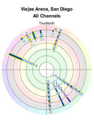
When looking at this radar image, the closer to the center, the higher the amplitude the television station. We can see the best areas to point the antennas would be northeast and southwest. While avoiding southeast, north-northeast, and west-northwest. You can use a compass (the iPhone has an app for that) to find the best placement on the day of the show, or with your stage drawings.
Final Thoughts:
As you can see, TVFool is a really great, FREE, tool that you can add to your RF road case. When it comes time to select the frequency bands for your next show, make sure you pull up the venue address in TVFool, that way you can make an accurate decision.
If you are looking for more information on how to do an RF Coordination from start to finish, make sure to check out this blog post and YouTube video: RF Coordination from Start to Finish