RF Coordination Training – Antennas
Last week I mentioned how we can do some pre-show prep with our wireless using TVFool.com, and if you missed it on the blog, make sure to check it out here! This week I want to talk about something that is fairly important when it comes to our wireless rig, and that is antennas.
Types of Wireless Antennas
Or antennae if you like to pronounce it that way! Antennas are to RF like microphones are to audio, it is our ‘transducer’ for our wireless products. RF is both made and received with the antenna, and as you can guess, there are a lot of different types of antennas out there. Let’s take a look at the main ones we see today:
Omni-Directional Antennas
¼ Wave Vertical Monopole
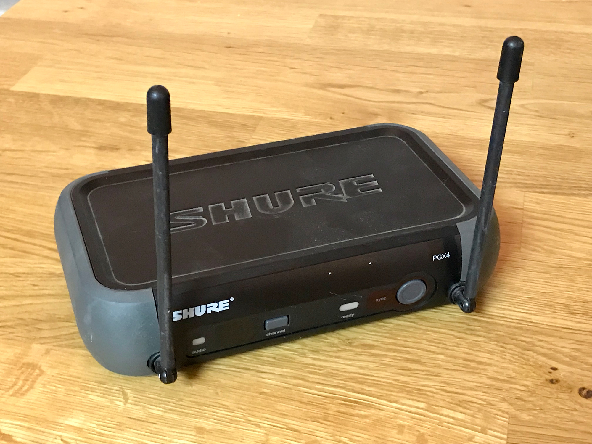
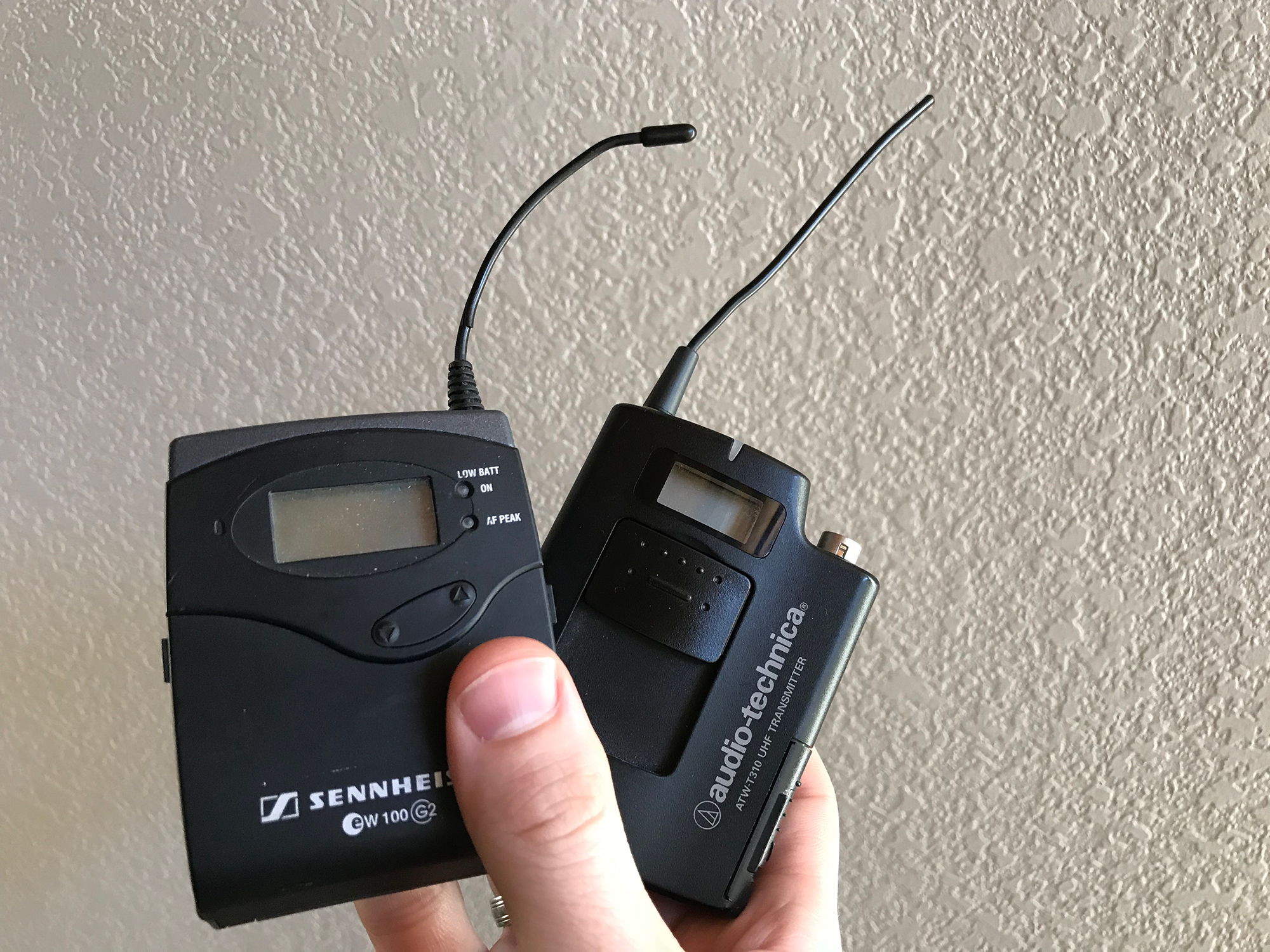
This is the most common antenna that is out in the audio marketplace. The ¼ wave vertical, ¼ wave monopole, or sometimes called a ‘rubber duck’ is as you can guess ¼ wavelength in length, and as the name suggests a ‘single pole’ meaning one side. The single pole is attached to the center conductor of the coax, and the ground is taken typically from the chassis of the wireless product. We see this most often on wireless IEM receiver packs, bodypack transmitters, or the small antennas that are connected to the back of the wireless rack receivers or IEM transmitters.
Because this antenna takes the ground from the chassis, it is not a good idea to mount this remotely away from the chassis.
(You can, however, mount this ¼ wave vertical onto a piece of metal that is at least ½ wavelength in length with the shield of the BNC connector grounded to the metal. Best practice is to have it in the middle of the piece of metal. But I would only do this if you didn’t have ANY other options)
½ Wave Dipole Antenna
The dipole is another very common antenna, similar to the monopole, just double the length! We now have a ¼ wave pole for the center conductor of the coax, and a ¼ wave pole for the ground, making ½ wave in length! The beauty of this type of antenna is that you can place it away from the receiver without any issues.
A really functional dipole is the Lectrosonics SNA600 that is an adjustable dipole antenna from 550-800MHz with 100MHz of bandwidth.
Shure also ships these with most of their higher end models like the Shure QLXD and the ULXD.
Wideband Omnidirectional Antennas
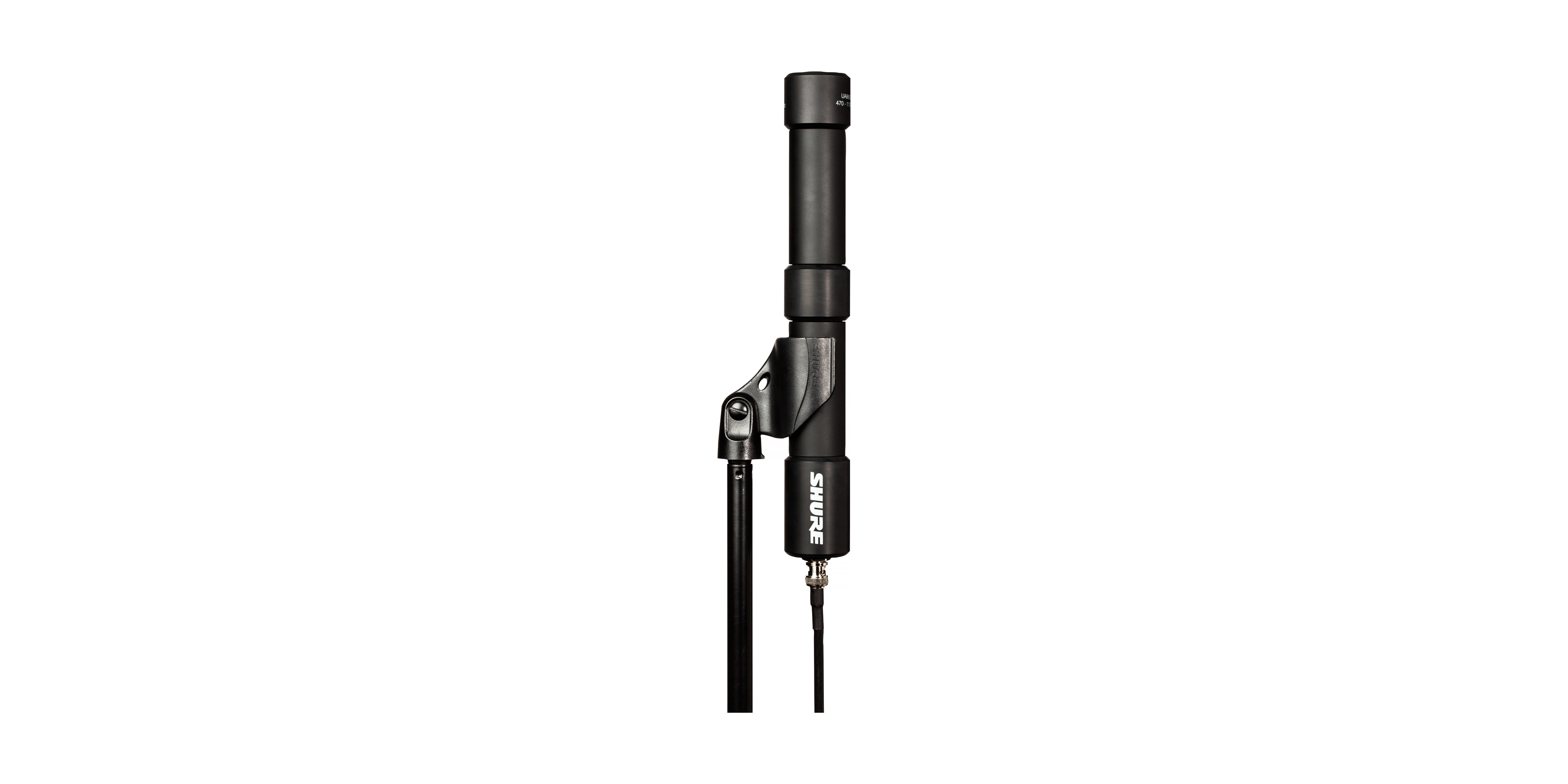
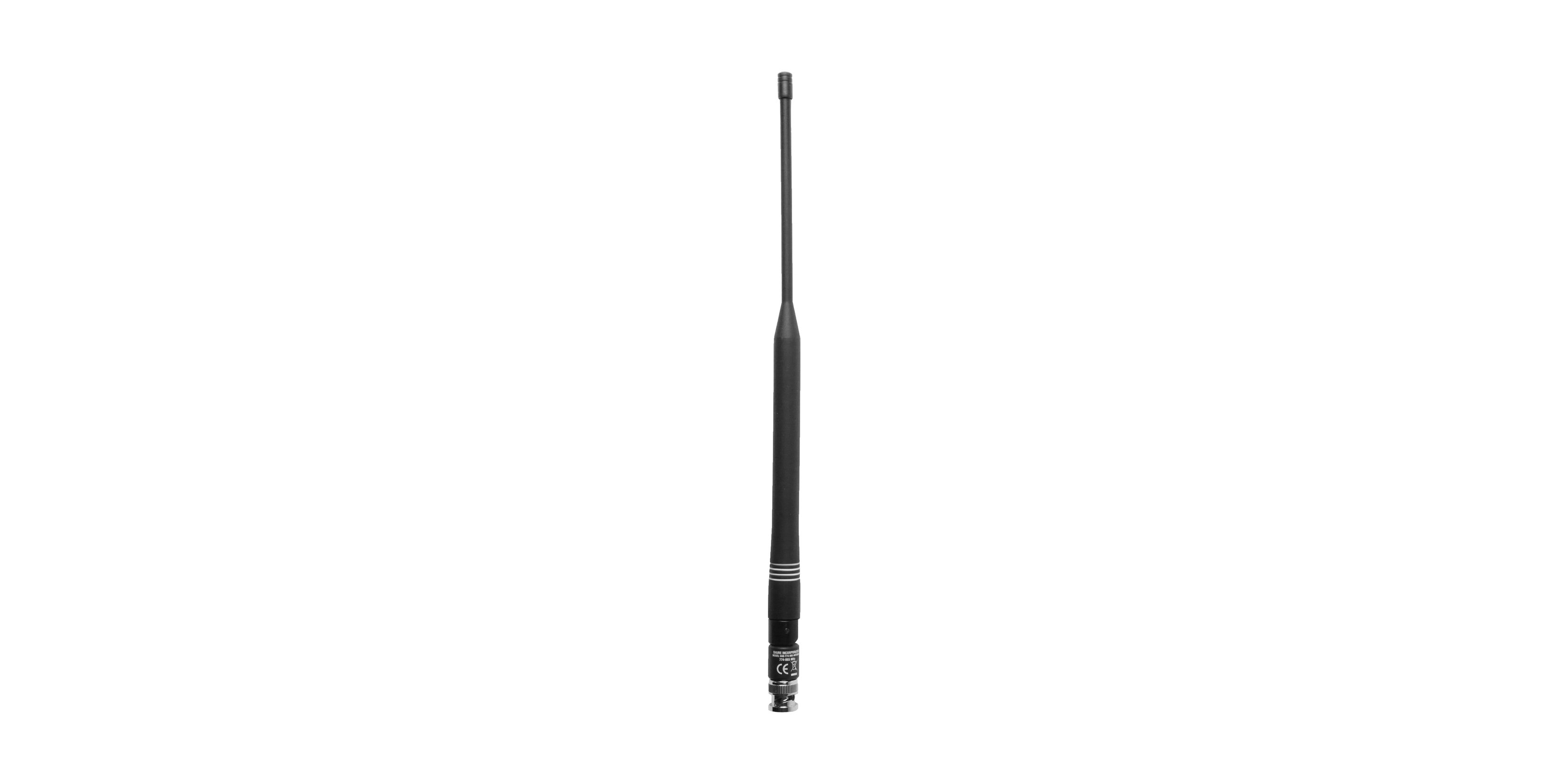
These are pretty cool antennas, and there are a lot of different designs out there. One of the most common that I see in the audio market is the Shure UA860SWB Wideband Dipole Antenna.
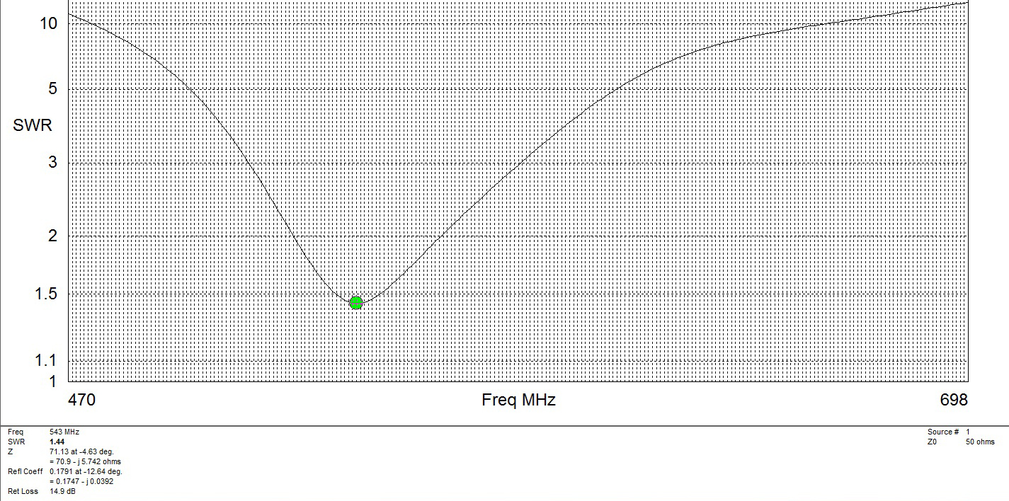
This design uses a thicker element to expand the bandwidth of the antenna. As we can see below, here is the bandwidth of an antenna tuned for 540MHz with an element the size of a 24 ga wire:
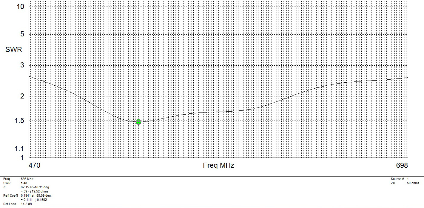
Here is the same antenna tuned for 540MHz just with an element that is 1.75 inches in diameter:
The principle is that the wider the element, the wider the bandwidth the antenna is able to use. By expanding the element from the 18 ga wire to the 1.5 inches, we have expanded the usable bandwidth of the antenna from 500-600 MHz to what we see below, 425MHz to well over 2.5GHz:
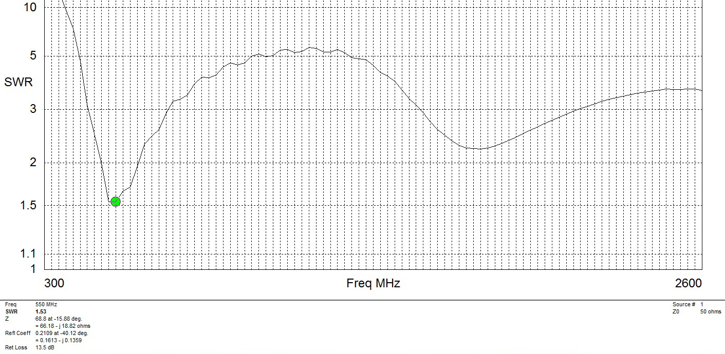
Typically when we are looking at an SWR plot like this, when the SWR is less than 5:1 it is considered adequate for an antenna.
Another type of wideband omnidirectional antenna is the Sennheiser A1031-U Wideband Passive Omnidirectional Antenna. This antenna is a wideband antenna made out of a PCB board.
Directional Antennas
Yagi (Yagi-Uda Antenna)
Not super popular in the audio community, but still a very common type of directional antenna in the VHF and UHF bands, the Yagi-Uda antenna has multiple parallel elements with a single ‘driven’ element toward the back. The rearmost element is around 5% longer than the driven element, this is called the reflector. The elements forward of the driven element are called directors and are 5% smaller as they go forward. The combination of the reflector and director elements gives this antenna forward gain to make it directional with a moderate amount of gain for its’ size. Each element is separated by ¼ wavelength, and as we add more elements, the overall gain of the antenna rises. The downside of this antenna is that it doesn’t have much of a wide-bandwidth capability.
Logarithmic Periodic Dipole Array
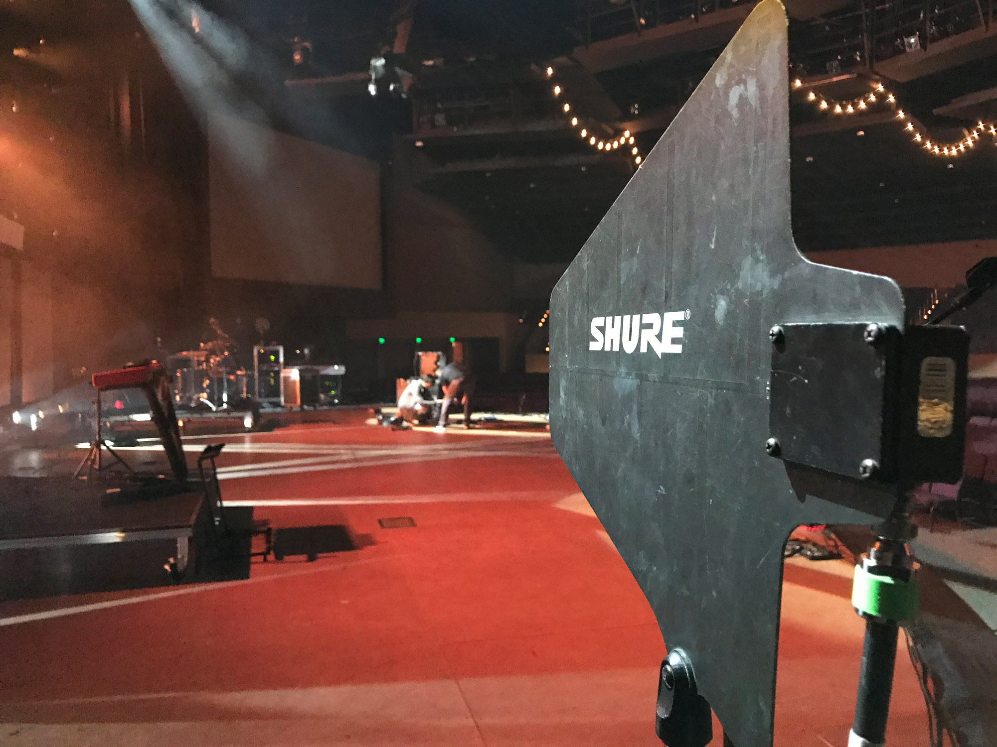
The logarithmic periodic dipole array also called: Log Periodic, LPDA, Paddle, Shark Fin, there are so many names for this one! This is a directional antenna using various sized elements on each side of the antenna center. It starts out larger toward the rear and the elements significantly reduce in length as they near the front. The various lengths of this antenna give it a very wide bandwidth and modest forward gain. While this antenna might not have as much gain as a Yagi antenna, having the wide bandwidth makes up for it.
This is the most common directional antenna you will find in the audio market. Here are a few of these over the various VHF/UHF spectrum:
- Shure UA874V – 174-216MHz (Active VHF Antenna)
- Shure UA874US – 470-698MHz (Active Antenna)
- Shure UA874XA – 902-960MHz (Active 900MHz Antenna)
- Shure PA805SWB – 470-870MHz (Passive Antenna)
- Shure PA805Z2-RSMA – 2.05-2.70GHz (For the GLX-D Advanced)
- Sennheiser A2003-UHF – 450-960MHz (Passive Antenna)
- RFVenue Diversity Fin Antenna – 470-698MHz (Passive Antenna with Dipole for Dual Diversity connections on one physical antenna)
Passive vs. Active Antennas
You will notice in the list above that there are a few antennas labeled ‘Active’ and a few labeled ‘Passive’. There is a bit of misunderstanding between these two, so I want to clear things up!
Active Antennas are antennas that have active circuitry attached to the antenna, typically these circuits are ‘low noise preamplifiers’ for boosting the receive amplitude. The main reason for these is to make up for coax loss between the antenna and the receiver. I’m going to go into transmission lines in a future blog post, but here is a quick chart to understand the loss that we see at 540 MHz:
| Coax Type | Loss over 100 Feet | Loss over 50 Feet | Loss over 25 Feet |
| RG-58 | -11.06 dB | -5.53 dB | -2.77 dB |
| RG-8X | -9.34 dB | -4.67 dB | -2.34 dB |
| RG-8 (Belden 9913) | -3.16 dB | -1.58 dB | -0.79 dB |
| LMR-400 | -2.96 dB | -1.48 dB | -0.74 dB |
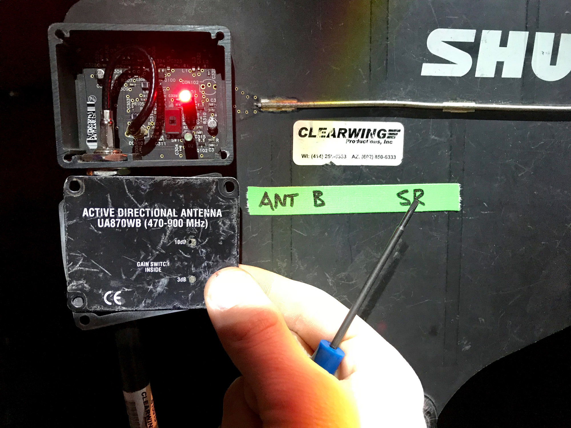
Typically, you will see on the active antennas a small switch (either internally or externally) and this will vary the amount of preamplifier gain that the antenna is boosting. We can see if we had a 100’ run of RG58, a +10 dB boost would be a good thing to have. Or over a 50’ run of RG58, a +6 dB boost would be sufficient.
Bias Voltage
Bias Voltage is one of those things that you can easily skip by in the equipment manual, but it is the one thing that powers our active antennas! If you have the option to turn it on and are using active antennas, you need the bias voltage for the active antenna to work. If you are using passive antennas, there is no need for the bias voltage to be on.
Basically, bias voltage sends a DC power down the antenna coax to the antenna, the antenna then uses that voltage to power the low noise preamplifier.
Okay, so why passive antennas?
Passive antennas allow us to transmit with the antenna. You see, the low noise preamplifiers with that ‘active’ antenna would burn up if an In-Ear Transmitter was applied to the antenna. Therefore, if you are doing any sort of transmitting, ONLY use passive antennas for the transmitter. If you are receiving, you can use either passive or active antennas.
Helical Antenna (Helix Antenna)
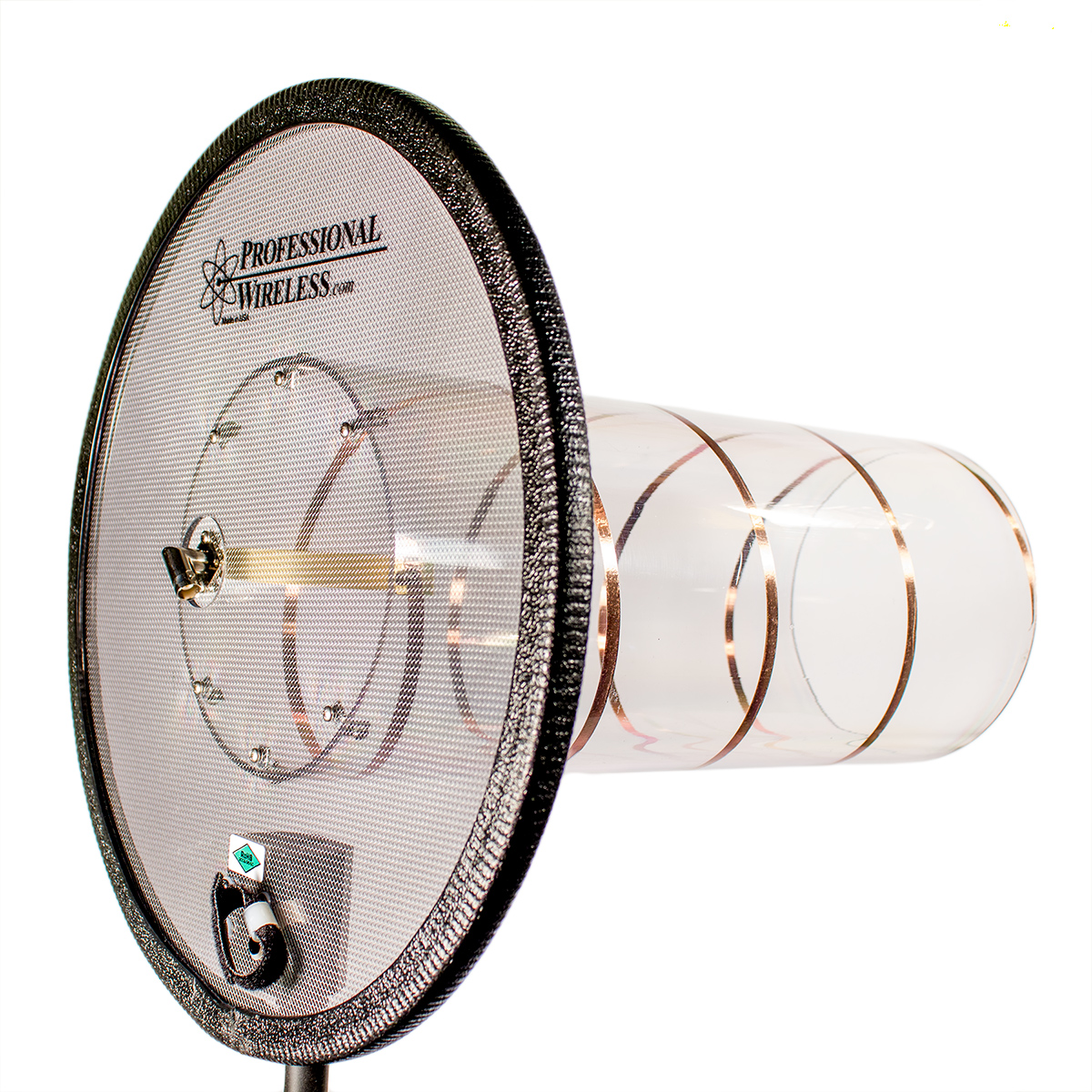
The Helical antenna is a broadband directional antenna where the transmitting element is twisted into a helix shape. Due to the shape of this antenna, the RF is sent out in what is called a circular polarized pattern.
Circular Polarization?
When we talk about polarization (and this is going to be super simplified), we are talking about the electromagnetic wave that is produced from the antenna. With a linear polarization, the wave travels in an ‘up and down’ fashion, this we would call ‘vertical polarization’. The best way to receive this would be to have another antenna oriented in the same way, up and down. But we can also take the antenna and turn it 90 degrees to its side. Now the electromagnetic wave is traveling ‘left and right’ thus forming a ‘horizontal polarization’.
Circular Polarization, on the other hand, is a bit more complex. These types of waves actually spin clockwise or counter-clockwise depending on how the antenna is built. Just like with the linear polarization, it is most beneficial to have a similarly polarized antenna on the other end for receiving.
So, why?
Circular Polarization provides a really cool benefit at the receiver, and this is why there are so many people/companies recommending this as a transmitting antenna for In-Ear Transmitters. To explain this, we need to talk about what theoretically happens when you take various polarizations and mix them.
| Transmitter Polarization | Receiver Polarization | Theoretical Loss in dB | Practical Loss in dB |
| Vertical | Vertical | 0 dB | 0 dB |
| Vertical | Slant (45 degrees off) | -3 dB | -3 dB |
| Vertical | Horizontal | -∞ dB | -20 dB |
| Vertical | Circular | -3 dB | -3 dB |
As we can see in the chart above, if we take a vertically polarized signal, and then start to take the receive antenna and make it more and more horizontal, we can theoretically reduce the RF wave to nothing. Now in practical terms, this loss is around -20 dB and can sometimes be less depending on multi-path (reflections in the room).
But when we take a look at the Vertical to Circular, we can see it is -3 dB. That measurement is at ANY angle. No matter WHAT we do with the antenna; vertical, slant, horizontal; the receive amplitude will always be -3 dB. Do you now see why this is beneficial with our musicians moving around a lot on stage? This is the main reason why antenna manufacturers will say there is less chance of dropout because the range of loss from polarization is always -3 dB. With a linear polarization, it could be anywhere from -0 dB to -∞ dB.
Back to the Helical Antenna

The Helical Antenna gives us a wide bandwidth, circular polarization AND a lot of gain. Therefore, this is one of the most popular antennas when it comes to having no issues with RF. The price tag of these antennas proves how great these are, with most being about twice the amount of an LPDA paddle antenna.
A few popular options are:
- RF Venue CP Beam – 470-698MHz (ultra-compact when folded down)
- Sennheiser A5000CP – 450-960MHz
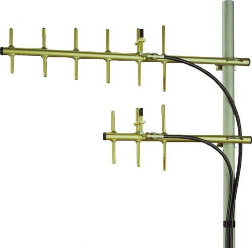
- Professional Wireless Helical Antenna – 460-900MHz
RF Doesn’t Care About Manufacturers
I have had a few people ask me if they need to switch out their antennas when swapping manufacturers of wireless equipment. As long as the old antenna is in the same frequency range as the new equipment, and the bias voltage is sufficient for the active antenna, then NO, you do not need to change antennas. I have used Sennheiser passive LPDA’s with Shure PSM1000’s a few times before because the rental house was out of stock on the Shure LPDA’s. As long as you are in the correct frequency range, you are good!
DIY RF Antennas
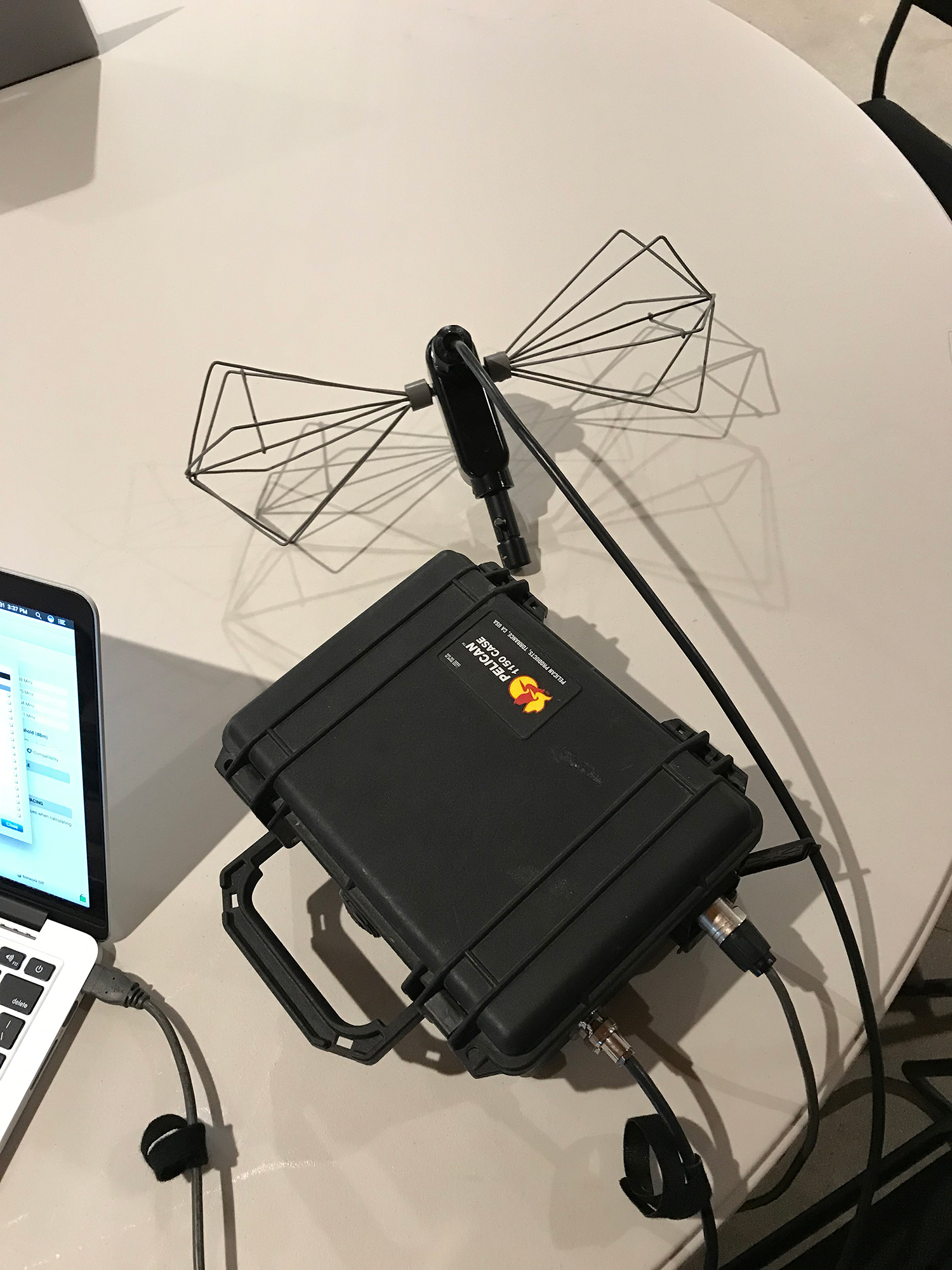
Being a ham radio operator, I have made quite a few antennas. One of my favorites is my Biconical Antenna that I use for my RF scanning when I am doing an RF Coordination.
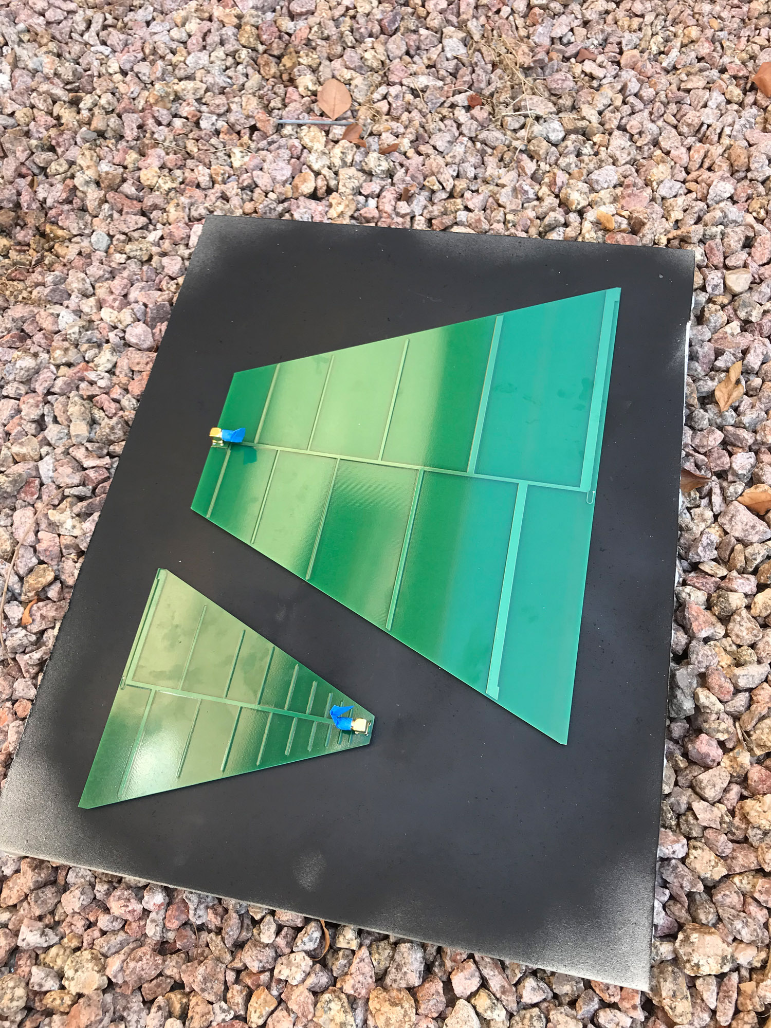
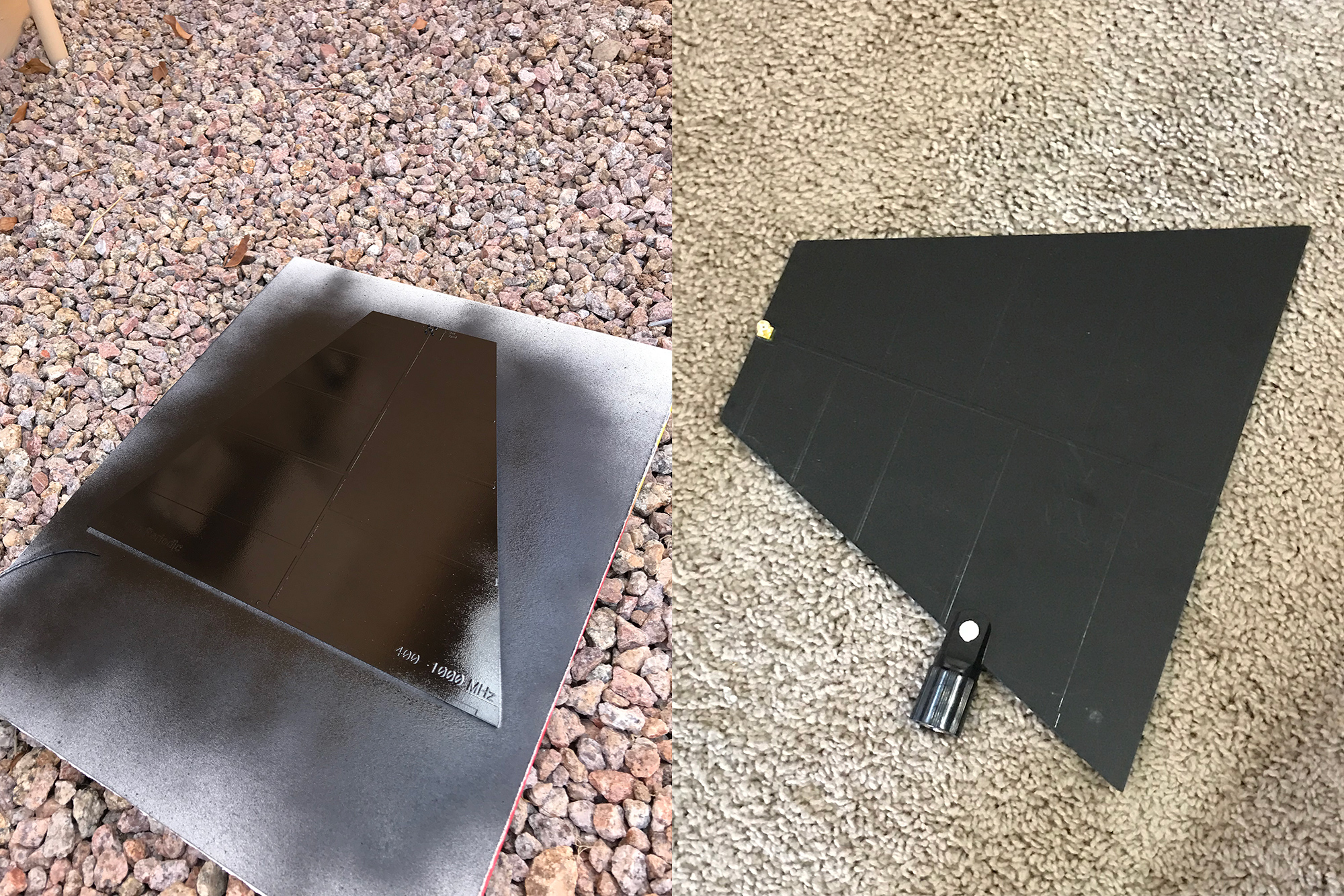
But there is one person that makes some fantastic antennas that I need to mention, and that is Kent, WA5VJB. You can find his products at www.wa5vjb.com and one specific product is the 400-1000MHz Log Periodic Antenna. This is a passive LPDA antenna just like the ones listed in this blog post, however, the cost is significantly cheaper. At the time of this blog post, the current price shipped was $29 per antenna. I have installed numerous of these antennas in churches in the past and have never had any problems with them.
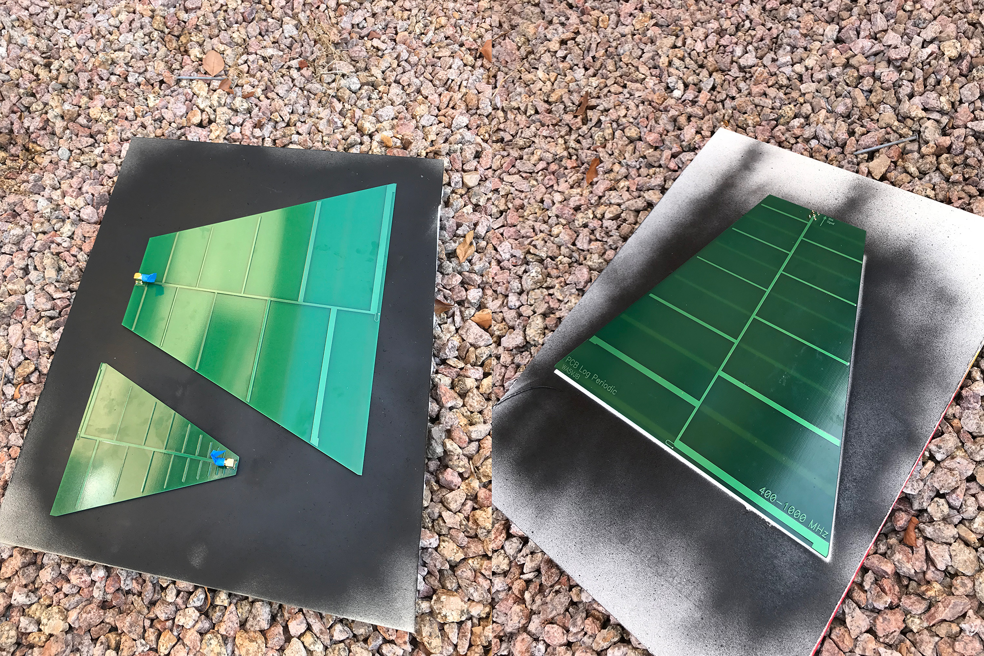
The only work you have to do, paint them black with a can of spray paint and solder an SMA connector on it. Lastly, figure out how to mount it! I have used gaff tape, a mic stand clip drilled through the antenna, and even a metal clamp to mount these.

Next time, Antenna Placement
Next time on my RF Coordination Training series, I am going to talk about antenna placement and how this can make a really big difference in how our wireless systems work.
If you are looking for more information on how to do an RF Coordination from start to finish, make sure to check out this blog post and YouTube video: RF Coordination from Start to Finish.