If I were to say that today’s topic is an easy concept, I would be lying. So, brew a pot of coffee, and start reading, because the topic of Intermodulation with Wireless Microphones is a tricky one. If you have been reading the blog for a while, you would have seen my series on Wireless Microphone Frequency Selection and how it can make or break your wireless system. If you haven’t started from the beginning, I would suggest taking a look here: LINK.
Intermodulation with wireless microphones – 3 Key Points!
- Intermodulation (IM) is a source of interference from the interaction between two or more signals at different frequencies when they are combined in a non-linear system.
- Intermodulation is also referred to as Intermodulation Distortion, IM, IMD, Intermod and Intermod Distortion.
- Intermodulation Distortion (IMD) is a measurement of the ratio (in dB) between the amplitude of the fundamental signals and the third-order distortion products.
HANG WITH ME EVERYONE! Now, wireless microphone transmitters and wireless microphone receivers have non-linear circuits in their design. When two strong signals mix in these non-linear devices, the signals will produce various sum and difference products which we call intermodulation.
Single Wireless Transmitter
A single wireless transmitter has a fundamental frequency, we are going to call that ‘F1’ and in today’s example that is 462.600 MHz. Now, that single fundamental frequency has harmonics at integer multiples of the fundamental frequency. For F1 the first harmonic would be 925.200 MHz (462.600•2). Another harmonic is at 1387.800 MHz (462.600•3). As the harmonics go up in frequency they decrease in amplitude.
Two Wireless Transmitters
Now we add a second wireless transmitter. This second wireless system must have a different frequency; ‘F2′ and is 462.700 MHz. Wireless receivers can only correctly demodulate one signal, so having a different frequency is a requirement with having more wireless systems.
F2 has its’ own harmonics, 925.400 MHz, another one at 1388.100MHz. However, not only do F1 and F2 have their own harmonics, but they also will interact with each other and cause spurious emissions inside the receiver (and sometimes the transmitter itself), this is where intermodulation occurs.
Intermodulation can cause problems with wireless receivers if they appear on, or adjacent to, a frequency that another wireless system is working on. The intermodulation products will cause the receiver to demodulate the wrong signal causing lots of audio issues. There are many different intermod distortion products that occur, the main to focus on being 2nd-order, 3rd-order and 5th-order distortion products. While other order distortion products are present, the amplitude and frequency are often too high in frequency and too little of amplitude to worry about.
Calculating Intermodulation Products
The main intermodulation products from two transmitters are calculated as such:
- [2nd order] = F2-F1
- [2nd order] = F1+F2
- [2nd order] = 2•F1
- [2nd order] = 2•F2
- [3rd order] = (2•F1)-F2
- [3rd order] = (2•F2)-F1
- [3rd order] = (2•F1)+F2
- [3rd order] = (2•F2)+F1
- [3rd order] = 3•F1
- [3rd order] = 3•F2
- [5th order] = (3•F1)+(2•F2)
- [5th order] = (3•F2)+(2•F1)
- [5th order] = (3•F1)-(2•F2)
- [5th order] = (3•F2)-(2•F1)
That is a LOT of math! I have made a graph below showing these IMD products below.
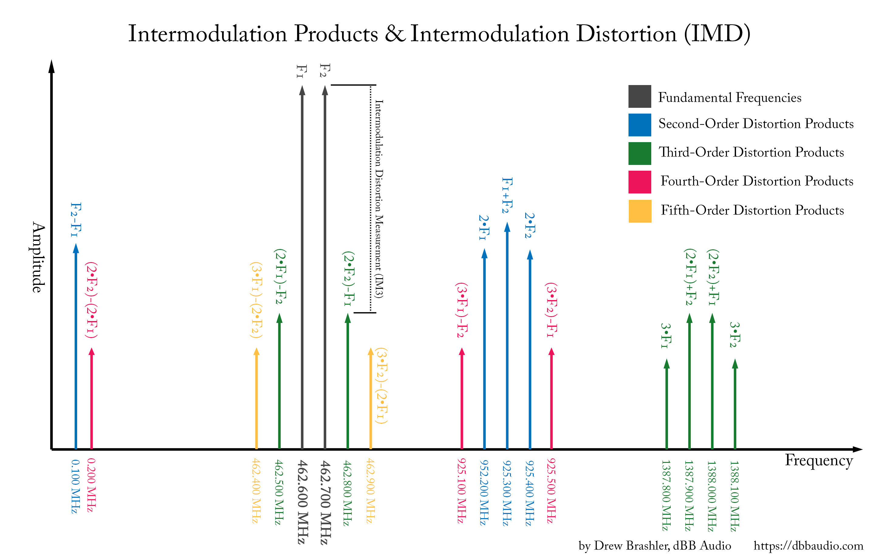
As we can see, the 2nd-order and 4th-order products around 0.200 MHz are not going to be much of a problem for us as we don’t have any wireless systems here. As for the 900 MHz range and the 1.388GHz range, these could cause issues if we were to add a system up in these bands. One thing to note is that most wireless receivers have some sort of RF band filtering to only pass a certain set of frequencies, so a 500Mhz receiver would have the RF filtering to not pass 900MHz or 1.3GHz into the mixer.
The main issue is the third-order products of (2•F1)-F2 and (2•F2)-F1, and the 5th-order products of (3•F1)-(2•F2) and (3•F2)-(2•F1). These four products (462.400, 462.500, 462.800 and 462.900) are still within the same band as the two wireless systems! So, if we were to add a third wireless system, we could accidentally place it on top of one of these spurious emissions and have interference occur.
IMD Nightmare
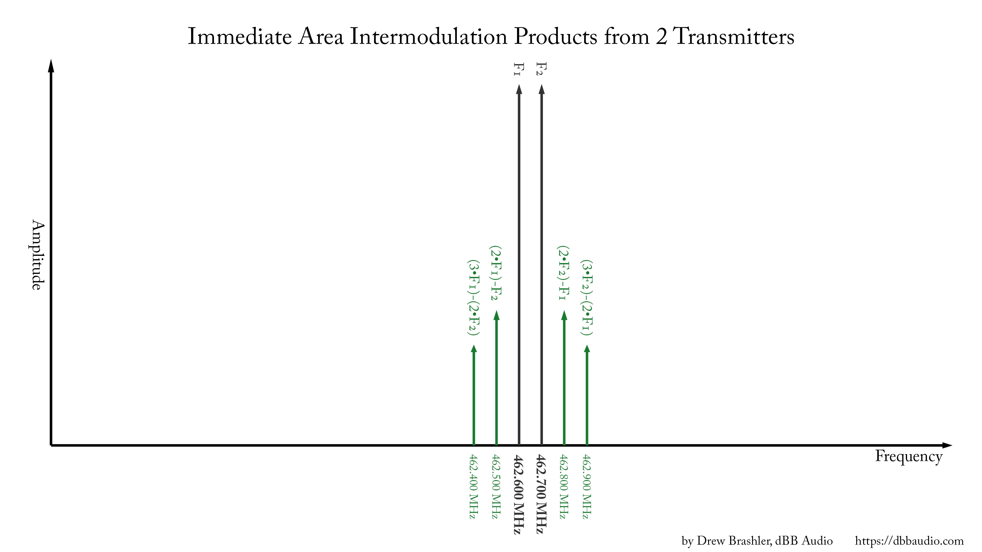
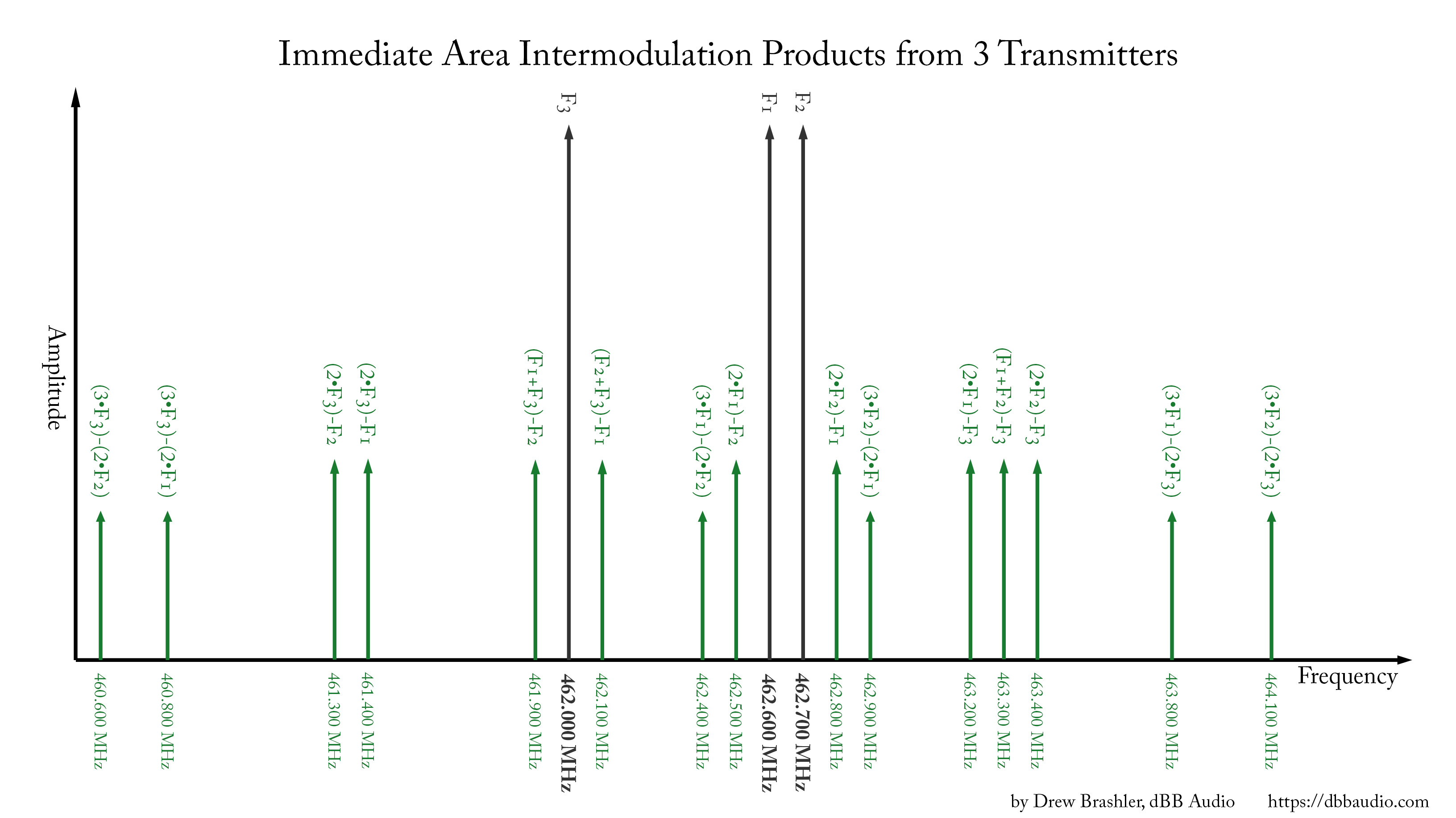
Every time we add a transmitter, the number of intermodulation products expands exponentially. In fact, when we have 3 wireless transmitters, the number of intermodulation products in the immediate area of our F1 and F2 expands from 4 to 15! I am not going to explain all of the math because that would take WAY too long, but you can imagine the math involved with trying to coordinate just 8 wireless systems all in one band; it would be hundreds of calculations!
Below we can see a graph showing the different intermodulation products with 2 transmitters vs 3 transmitters:
Demonstration of Intermodulation with Wireless Microphones
It is one thing to show the math and fundamentals of intermodulation with wireless microphones, but it is really fun to watch it! So, I have a YouTube video for you to check out where I have two transmitters matching the frequencies of F1 and F2 and I will show you the intermodulation actually occurring! Check it out!
How do we fix it?
The best advice is to always use wired systems whenever possible. Does your drummer REALLY need a wireless in-ear monitor system as he sits on his drum throne? If you do need to use a wireless system, always consult the manual to find the channels the manufacturer suggests to use together. They will have already performed the math and testing to make sure these frequencies work well together.
Another main thing is to try to separate your wireless transmitters. The closer two transmitters are together, the stronger the IMD will be. If you need to place two wireless body packs on a person, place them on opposite sides of their body. Also, asking singers to not lean in together with their microphones will help.
Lastly, when your musicians come off stage, have them turn off the transmitters before setting them into a pile. Having a single metal bread tin for each wireless product when they are not being used is a great way to keep RF interference at a minimum! The metal bread tin acts as a faraday cage and will keep the RF more contained while backstage.
NO MATH NEEDED – Shure Wireless Workbench 6!
Leave your calculators at home! Luckily, we have computer software available to us to calculate all of the potential intermodulation. This software will even let you select the brand and type of wireless systems you have and it will coordinate the correct frequencies depending on all of the parameters you input. Best of all… it’s FREE!
The software is called Shure Wireless Workbench 6 and it can be downloaded here.
Next time, I will talk about how we can use this software AND how we can combine those inexpensive RF spectrum analyzers to let us give accurate frequency coordination in our churches or venues!