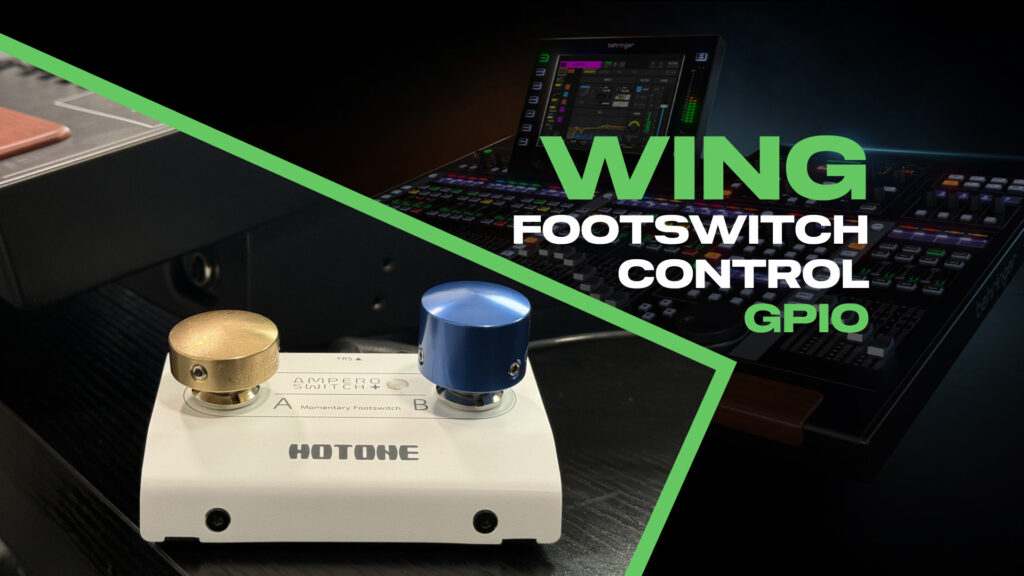
If you have ever been looking at the back of the Behringer WING and seen the ports labeled GPIO, and wondered, what are those? Well this is the post for you! GPIO stands for General Purpose Input/Output. In a practical sense, the Behringer WING GPIO ports let you connect a footswitch to trigger any function you can assign to a custom control button. This is incredibly useful for monitor engineers who need hands-free talkback, show callers making VOG (voice of god) announcements, or anyone who wants physical buttons beyond what’s on the console surface.
GPIO on the Behringer WING can function with any of the Custom Controls that you can assign to a button. For a complete reference of every function you can assign, check out my WING Custom Controls Reference.
Also, you can watch the full walkthrough in my WING GPIO setup video on YouTube.
What is GPIO?
GPIO stands for General Purpose Input/Output. On the WING, GPIO serves two purposes:
- Input: Use an external footswitch or button to trigger console functions
- Output: Use the console to trigger external devices like on-air lights, amp relays, or power sequencers
Each GPIO connection uses a 1/4″ TRS jack, and each TRS jack carries two GPIO channels (one on Tip, one on Ring).
GPIO Count by Model
- WING Full Size: 2 TRS jacks = 4 GPIO
- WING Rack: 2 TRS jacks = 4 GPIO
- WING Compact: 1 TRS jack = 2 GPIO
Physical Connection
Connect a TRS cable from your footswitch’s output to the GPIO jack on the back of your WING. A dual footswitch like the Hotone Ampero Switch+ gives you two buttons on a single TRS cable, which maps perfectly to the two GPIO channels per jack.
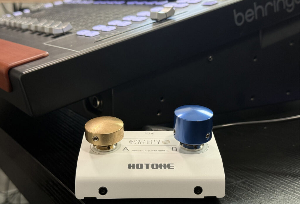
The Hotone Ampero Switch+ with Barefoot Button covers (Small Brass) (Large Blue).
Accessing GPIO Settings
Press ‘Setup’ twice to open the Custom Controls page, then tap ‘GPIO’ on the screen. This shows GPIO 1 and GPIO 2 (or all four on the Full Size and Rack).
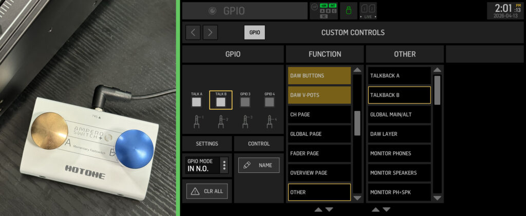
The GPIO configuration screen showing mode and function options.
GPIO Modes Explained
Each GPIO can be set to one of six modes. The first four are input modes (for footswitches), and the last two are output modes (for controlling external devices).
Input Modes
TGL N.O. (Toggle, Normally Open) Press once to activate the function, press again to deactivate. Use this for functions you want to toggle on and off, like engaging a mute group or switching scenes.
TGL N.C. (Toggle, Normally Closed) Same toggle behavior as the Toggle, Normally Open, but the action triggers in the opposite way. This is useful if you have a normally closed switch and want toggle behavior.
IN N.O. (Input, Normally Open) Momentary mode. The function is active only while you hold the button down, and deactivates when you release. This is the classic “push to talk” behavior for talkback.
IN N.C. (Input, Normally Closed) Momentary mode, but inverted. When pared with a normally open switch, the function is active when the button is NOT pressed, and deactivates when you press it. This creates “cough switch” behavior, or can be used to invert a mute function into an unmute function.
Output Modes
OUT N.O. (Output, Normally Open) The GPIO output acts as a switch that is normally disconnected. When you trigger the assigned function, the switch closes (connects). Use this to trigger external devices that expect a contact closure to activate.
OUT N.C. (Output, Normally Closed) The GPIO output acts as a switch that is normally connected. When you trigger the assigned function, the switch opens (disconnects). Use this for devices that expect an open circuit to activate, or for fail-safe configurations where you want the circuit closed by default.
The GPIO output is just a simple switch closure with no voltage. Connect it to relays, power sequencers, on-air lights, or any device that accepts a contact closure trigger.
Normally Open vs Normally Closed Switches
Before diving into the examples, it helps to understand the difference between normally open (N.O.) and normally closed (N.C.) switches.
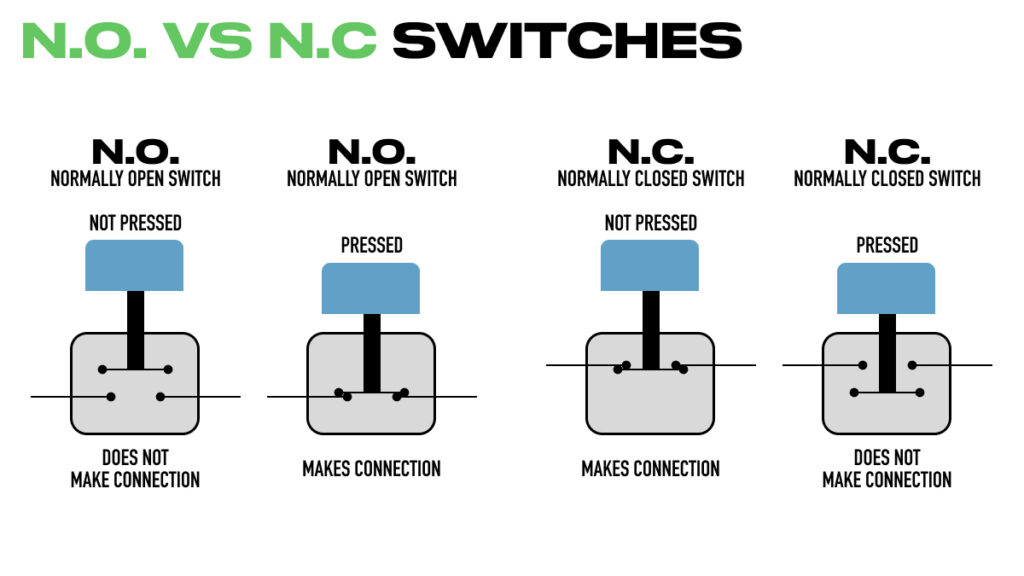
Normally open switches make connection when pressed. Normally closed switches break connection when pressed.
Normally Open (N.O.): The circuit is open (disconnected) when the switch is at rest. Pressing the button closes the circuit and makes the connection. Most footswitches and guitar pedal switches are normally open.
Normally Closed (N.C.): The circuit is closed (connected) when the switch is at rest. Pressing the button opens the circuit and breaks the connection.
If you’ve used keyboard sustain pedals, you may have noticed that different brands expect different switch types. Yamaha keyboards typically expect normally closed pedals, while Korg-style footswitches are normally open.
Matching Your Switch to the GPIO Setting
The general rule is to match the GPIO setting to your switch type. If your footswitch is normally open, use the N.O. settings. If it’s normally closed, use the N.C. settings.
However, there’s an important exception: when you want to invert the behavior of a function. For example, if you want a “press to unmute” switch, you’d use IN N.C. with a normally open footswitch. This inverts the mute function so that pressing the button unmutes the channel instead of muting it.
GPIO Input Mode Reference Chart
Momentary Modes (IN)
| GPIO Mode | Switch Type | Button Not Pressed | Button Pressed |
| IN N.O. | N.O Switch | Not Active | Active |
| IN N.O. | N.C. Switch | Active | Not Active |
| IN N.C. | N.O Switch | Active | Not Active |
| IN N.C. | N.C. Switch | Not Active | Active |
Toggle Modes (TGL)
| GPIO Mode | Switch Type | Toggle Fires |
| TGL N.O. | N.O Switch | On Press Down |
| TGL N.O. | N.C. Switch | On Release |
| TGL N.C. | N.O Switch | On Release |
| TGL N.C. | N.C. Switch | On Press Down |
Practical Examples
Scene Control (Go Previous / Go Next)
Assign GPIO 1 to ‘Go Prev Scene’ and GPIO 2 to ‘Go Next Scene’ from the Show Control category. Set both to IN N.O. This gives you hands-free scene navigation during a service or show.
Settings:
- GPIO 1: IN N.O. > Show Control > Go Prev Scene
- GPIO 2: IN N.O. > Show Control > Go Next Scene
Talkback A and B for Monitor Engineers
This is my favorite use for GPIO. Assign one button to Talkback A (band only) and one to Talkback B (band plus PA). As a monitor engineer, you can communicate with musicians without taking your hands off the console.
Settings:
- GPIO 1: IN N.O. > Other > Talkback A
- GPIO 2: IN N.O. > Other > Talkback B
One thing to note: the talkback switch mode setting in the Monitor section (latching, auto, or momentary) is independent of the GPIO setting. If you have talkback set to ‘Auto’ or ‘Latching’ on the console, pressing the physical talkback button will still follow that behavior. But the GPIO input will always follow the mode you’ve assigned (IN N.O. = momentary, TGL N.O. = toggle).
VOG Unmute Switch for Show Callers
For a show caller or producer making Voice of God announcements, give them a footswitch that unmutes their mic channel when pressed. The key here is using IN N.C. with a normally open footswitch to invert the mute behavior.
Settings:
- GPIO 1: IN N.C. > CH Mute > CH 1 (or whichever channel is the VOG mic)
With this setup, the channel stays muted until the show caller presses the footswitch. While held, the channel is unmuted. When released, it mutes again.
The big advantage of controlling the mute this way is that there’s no clicking in the audio path. Since you’re muting and unmuting the channel digitally rather than switching an analog signal, the transition is completely clean.
Recommended Gear
I picked up a simple dual footswitch from Sweetwater that works great for this:
- Hotone Ampero Switch+ Passive Dual-footswitch Controller
- Barefoot Buttons V1 Standard Footswitch Cap – Brass
- Barefoot Buttons V1 Tallboy Footswitch Cap – Dark Blue
The Barefoot Button covers make it easy to feel which button you’re pressing with your foot without looking down.
YouTube Video
Watch the full walkthrough in my WING GPIO setup video on YouTube.